
The Axis document window is used to display and modify a specific axis. The window can be opened from the context menu of an axis in the Axes window or from the context menu of an axis displayed in the context panel of the domain window in the Context tree of the Domain Explorer.
You need the domain permission Read (0) on the domain the axis belongs to to open the axis window for this axis. To modify an axis you need the domain permission Manage axes (10) on the domain the axis belongs to.
The geometrical shape of an axis is defined by a series of axis points. Axis points cannot be keyed in directly but are imported from a text file. Selecting Import axis points from file from the windows toolbar brings up a windows modal form that allows you to select a source file from your file depot. Select OK to import the data. A summary of the import will be shown in the Output Window. See chapter Axis points import file format for a description of the file format.
On the General tab of the axis window you can define basic properties of an axis. The ID is the internal (Redbex) ID of the axis The axis Name is mandatory, it is recommended to use axis names that are unique across all domains. If you have numerous axes defined it might be helpful to order the axes using the Path.
Specification of the Coordinate system is mandatory. The setting defines on which coordinate system the axis definition is based, i.e. in which coordinate system the axis points are expressed. Note that changing the axis coordinate system is possible for existing axis but it will give the already defined axis points a different real world position.
The First axis point sloped offset and First axis point horizontal offset boxes are used if the geometrical definition of the axis describes only a part of the axis. The unit for these numerical values is the unit for length measurement in the underlying projected coordinate system.
The Simplification tolerance value is also expressed in the length measurement units of the underlying coordinate system. For more information about axis simplification see chapter Axis simplification. A simplification tolerance lower than zero or will disable simplification, a simplification tolerance equal to zero will only simplify exactly straight parts of the axis.
The Summary tab shows a simple graphical representation of the axis, i.e. a 3D poly-line connecting all axis points. Below the visualization a summary of the axis geometry is displayed. Table 1 explains the data shown in this summary.
Datum |
Explanation |
Original axis point count |
The number of axis points stored for this axis |
Reduced axis point count |
The number of points used in the simplified axis. If Simplification tolerance is set to zero this will always be the same as the original axis point count. |
Horizontal axis length |
The length of the geometrically defined axis (without the offset specified for the first axis point) projected to the XY plane, given in the length measurement unit of the underlying coordinate system. |
Sloped axis length |
The length of the geometrically defined axis (without the offset specified for the first point) given in the length measurement unit of the underlying coordinate system. |
First axis point |
X, Y and Z Coordinates of the first geometrically defined axis point, given in the length measurement unit of the underlying coordinate system. |
Last axis point |
X, Y and Z Coordinates of the last geometrically defined axis point, given in the length measurement unit of the underlying coordinate system. |
Table 1: Data shown in the axis summary.
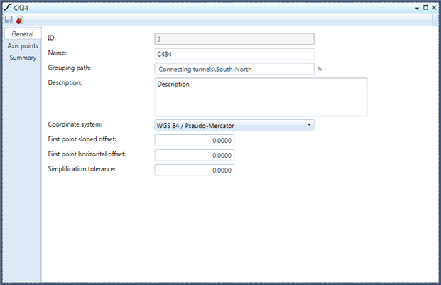
Figure 1: The General tab of the axis window
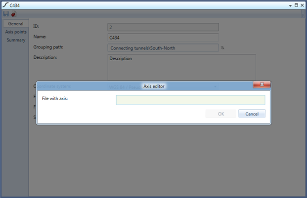
Figure 2: The window modal dialogue to import axis points
